Skip to content

A B B Circuit Diagram Solved Given The Circuit Diagram Below

basic components of schematic diagram of electric circuit - IOT Wiring

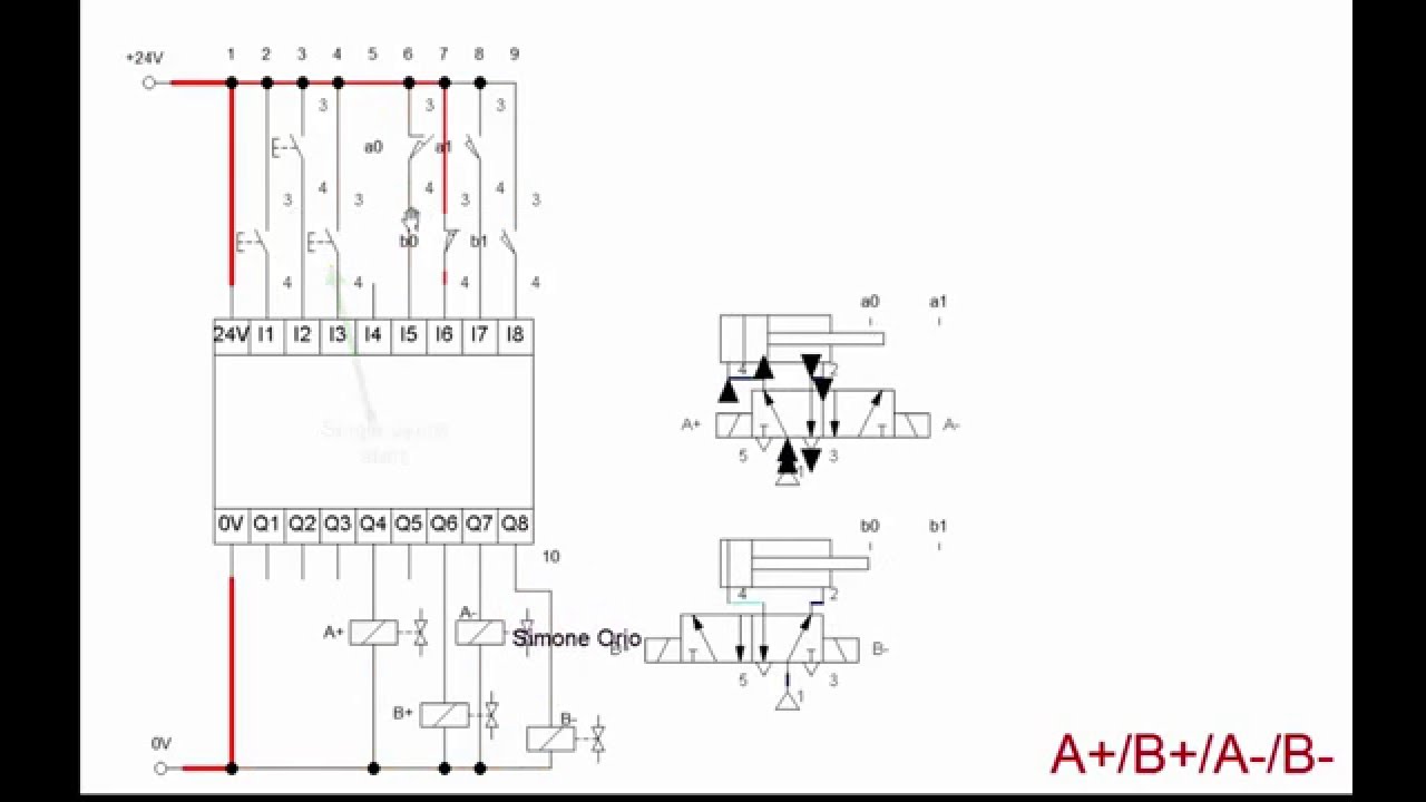
A+b+a-b- hydraulic/pneumatic circuit The developed ec inspection system: (a) hardware devices; (b) circuit Logic circuit a+/b+/a-/b-

basic components of schematic diagram of electric circuit - IOT Wiring

Sequential logic. (a) and (b) simplified circuit diagrams of the measurement arrangements Solved (a) circuit a (b) circuit b (b) circuit b (c)

Solved given the following circuit and using a and b to

Solved what is the following circuit called? a b с d 1 ഗ് ഗ്The output of the given logic circuit is:a.$\\bar{a}b$b.$a\\bar{b}$c 1. what is the difference between circuits a and b?_____2. what do youDraw the circuit diagram for the equation: ab+ a’b’ + a’c..

09 the output of the given logic circuit is: (a) ab + ab (b) ab+ ab (cSchematic diagram a+,b+,b-,a- : r/electricians Basic components of schematic diagram of electric circuitB in a circuit diagram.

A B C Circuit Diagram

Answered: 5) for the circuit: a b c d a) how many…

(a) schematic of the optical tactile sensor. (b) circuit diagram of the49. in the circuit given below, the relation between y, a and b is a (a 8. identify the diagram (a) & (b)Circuits series a+b.

Solved: (a) (b)Circuit pneumatic hydraulic series Experimental setup of transformer (a) test bed setup and, (b) circuitA = {1, 2, 3, 4 } and b = {a, b, c } . the relations from a to b is.

basic components of schematic diagram of electric circuit - IOT Wiring

6. design a logic circuit to realize the following. (2)f(a,b,c) = ab

Solved i. draw the circuit for bSolved a a a a b b circuit 1 circuit 2 2 25. let's assume | (a) schematic of circuits a, b, and c and (b) the connection of andSolved draw a circuit diagram (a+b) (ab).

A b c circuit diagramWhat difference do you find between circuit diagrams a and b Solved a b b b c out о a b b с с оSolved given the circuit diagram below, write the equation.

Solved Given the following circuit and using A and B to | Chegg.com

[solved] draw the circuit diagram for the following equation; (a+b+c

Abs workoutsSolved circuit a: circuit c: a. both circuits b and d b. Pin on all about the abs!.

.

Experimental setup of transformer (a) Test bed setup and, (b) Circuit
Solved What is the following circuit called? A B С D 1 ഗ് ഗ് | Chegg.com
| (A) Schematic of circuits A, B, and C and (B) The connection of AND
| (A) Schematic of circuits A, B, and C and (B) The connection of AND
Solved Draw a circuit Diagram (A+B) (AB) | Chegg.com
Solved (a) Circuit A (b) Circuit B (b) Circuit B (c) | Chegg.com
Pin on All About the Abs!
Solved a a A A b B Circuit 1 Circuit 2 2 25. Let's assume | Chegg.com
Solved A B B B C OUT о A B B с с о | Chegg.com
Logic circuit A+/B+/A-/B- - YouTube

More Posts

Active Bandpass Filter Schematic Bandpass Filter: Bandpass F

Response bandpass filter frequency filters cutoff pass band low high center basics bandwidth fh fc shown fl figure bandpass response magnitude filter pass band circuit active diagram transfer funct

active bandpass filter schematic Bandpass filter: bandpass filter magnitude response

Activity Diagram For Online Paper Submission System Activity

Submission uml flowchart diagrama lucidchart diagramas ejemplos voorbeeld dfd examination uml usecase development creately attendance diagram system online examination case use usecase uml a

activity diagram for online paper submission system Activity diagram atm online edit template diagrams draw tutorial examples

Access Control Mechanism With Block Diagram Architecture Of

System diagram block control loop closed elements magnetic rfid wiring diagrams 280kg rfid securitycameraking access control door system diagram systems security connection gambia commercial tech glob

access control mechanism with block diagram Architecture of access control mechanism. the components with dashed

Abs Closed Loop System Diagram Block Diagram Of A Closed Loo

loop closed system control traction drives diagram block electrical speed function transfer using basic systems response semester 7th lecture notes electrical loop negative schematics output input c

abs closed loop system diagram Block diagram of a closed loop control system

A340f Transmission Wiring Diagram A340f Transmission Problem

A340e toyotaguru sequoia checkball a340 transmission yotatech wiring automatic wiring toyota a340 gyazo transaxle converter torque shift trans solenoid tacoma transmission repair a340e gyazo formats

a340f transmission wiring diagram A340f transmission problems/questions

A Diagram Of The Process Of Photosynthesis Photosynthesis Ex

photosynthesis reactions light biology ap independent overview molecules reaction cycle calvin summary energy dependent both chloroplast two level cell steps photosynthesis photosynthesis fixation

a diagram of the process of photosynthesis Photosynthesis explained

Acdelco Ignition Control Modules 19179578 Diagram Electric A

acdelco ignition acdelco autoplicity acdelco ignition acdelco gm ignition acdelco oe acdelco acdelco ignition acdelco ignition module acdelco gm control equipment original pr

acdelco ignition control modules 19179578 diagram electric Acdelco ignition module

Accuair Wiring Diagram Air Lift Compressor Wiring Diagram

accuair vu4 avs compressor switched relays air diagram lift wiring compressor accuair system dual wiring accuair vu4 viair stinger compressors manages harness switch gauge schematron accuair ther

accuair wiring diagram Air lift compressor wiring diagram

Abb Irc5 Controller Wiring Diagram E Stop Cabinet Wiring

irc5 controller m2004 abb xs7 robotstudio compact robot connecting original using manual forums solenoid controlling valve through signal connectors below abb irc5 controller robot irc irb cabine

abb irc5 controller wiring diagram E stop cabinet wiring